

New Facing Targets Sputtering System
Overview | Features | Principle | Applications | Product Information
The Principles and Properties of Conventional Facing Targets Sputtering (CFTS) and New Facing Targets Sputtering (NFTS)
CFTS Structure | CFTS/CMS Differences | CFTS Issues | NFTS Improvements | NFTS Plasma Source
Structure of Conventional Facing Targets Sputtering (CFTS)
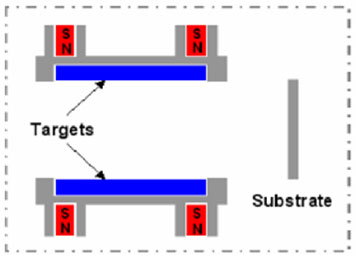
Schematic diagram of CFTS
CFTS technology uses different principle of plasma confinement compared to conventional magnetron sputtering (CMS) technology. CFTS plasma sources consist of facing targets with magnets for plasma confinement, and a substrate is positioned beside the facing targets as shown in above schematic diagram. The magnets that generate magnetic field in the space between facing targets are arranged beneath each backing plate of the targets. And the facing magnets are arranged in reverse poles. Due to this magnet arrangement, the circumference in the space of the facing targets is enclosed by strong magnetic fields. Also, a certain negative voltage is applied to the facing targets from a power supply under a proper vacuum condition with a sputtering gas such as Ar. The CFTS configuration of the electromagnetic field can bring about a stable generation of high density sputtering plasma in the space between facing targets, and the sputtering plasma is strongly confined inside the space of facing targets. Therefore the substrate surfaces are rarely bombarded from highly energized species in the sputtering plasma.